
The warmth carrier decreases in volume after the action of the air purgers in the heating system because of freeing air. Cleaning the filters from slime and mud also decreases the volume of the warmth carrier. In addition, different temperature regimes, resulting from different outside temperatures leading to increasing or decreasing warmth loss from the building, lead to periodic changes in the operating mode of work of the boiler burner. Sometimes it heats the water intensively, then proceeds in an economical mode. Such periodic work cycles can lead to sudden jumps in pressure in different parts of the system and to activation of the safety valves. Finally, in the heating system, the collet connections can simply loosen and a leak of warmth carrier can start. To avoid accidents in the heating system, constant volume of warmth carrier and constant pressure must be maintained at the level recommended by the boiler manufacturer. This is done with the help of automatic replenishment units.
The main item in the automatic replenishment unit is the pressure reducing valve (see Figure 38). The valve is equipped with a membrane under the pressure of water «behind the device». By adjusting the tension of a spring, the required water pressure is attained and the membrane is positioned in the upward state, and compresses the spring. When the pressure in the heating system falls (behind the valve) the water stops pressing the membrane and the spring pushes the valve stem downwards, opening a hole in the valve saddle. The water from the water supply system runs through the opened hole into the heating system pipe. By reaching the nominal pressure, the membrane bends upwards and through the stem and closes the saddle of the valve with the cone. It should be noted that the pressure reducing valve of the replenishment unit is quite often in the open state. It works every time the automatic air purgers are triggered. And since the air from the heating system is removed almost constantly, therefore the replenishment valve opens quite often.

To prevent the dirty water from the heating system from getting to the water supply system, a check valve is installed after the pressure reducing valve. It can be integrated into the housing of the pressure reducing valve or installed as a separate item. Modern ecological requirements suggest that a check valve or a flow interrupter be installed before the pressure reducing valve. The flow interrupter is also a kind of check valve, but more sophisticated: it consists of two check valves and a drain pipe between them. Modern European regulations require the installation of a flow interrupter as a «must do» thing because the warm water which goes from the heating system into the water supply system contributes to the development in the pipes of various bacterial life forms and then these bacteria settle on the walls of the water pipes.

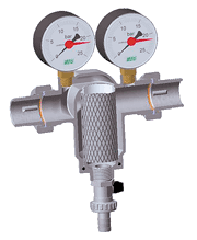

To soften hard water and thereby prevent scale from accumulating in the heating system, a water treatment filter is installed before the pressure reducing valve. In budget variants, the water treatment filter can be replaced by a conventional mesh filter or mud filter. Mesh filters (see Figure 39) without a transparent bulb can be fitted with manometers which allow the water pressure to be monitored in front of and behind them, and by the drop in pressure, you can judge the degree of contamination of the filter. It is recommended that a bypass to the whole replenishment unit be installed using ball valves. If suddenly the replenishment unit or some of its elements is damaged, then while it is being repaired, a single replenishment of the heating system can be done via the bypass. Furthermore, the filters can be washed out with counter-flow through the bypass (see Figure 40).

The most ideal place for installing the replenishment unit in the heating system is the point where the expansion tank is installed, which is considered the «zero» reference point for the whole heating system. If the replenishment unit is installed at this point, then the pressure reducing valve works most accurately. However, in practice, such a connection of the replenishment unit is too close to the boiler. The tap water mixing with the return water cools it and comes to the boiler with too low a temperature, and this affects the working of the boiler negatively. Therefore when connecting the replenishment unit close to the boiler, it is recommended to «put» the replenishment unit on the system of hot water supply or move it away from the boiler so the cold water from the water supply is well mixed with the return water and get warmed.
In suburban houses with poor or irregular water supply, a storage hydro-accumulator is installed before the replenishment unit. Usually, with a normal water supply, the water pressure in the water supply system exceeds the pressure in the heating system and the replenishment unit works in automatic mode. If the water pressure in the supply is less than that of the heating system, then the pressure reducing valve will not work. In this case, the installation of the hydro-accumulator is required. A hydro-accumulator can be of two types: either it is an ordinary container installed somewhere in the attic, or a membrane tank that resembles an expansion tank. As a rule, a heating system does not need its own hydro-accumulator. So the replenishment unit is connected to the water supply accumulator of the whole house.


